Monday, June 11, 2018

Experiment 8 Magnetic Fields

Experiment 8 Magnetic Fields
Topic: Magnetic Fields
Title: Earth's magnetic field
Objective: To estimate the horizontal component of the Earth's magnetic field
Theory:
Figure 11 shows a circular loop of radius R and carry current I situated at distance x from a fixed point P.
Experiment 7_Pic4
Figure 11
The magnetic flux density B at P is
<math xmlns="http://www.w3.org/1998/Math/MathML"><mi>B</mi><mo>=</mo><mfrac><mrow><msub><mi>&#x3BC;</mi><mn>0</mn></msub><mi>I</mi><msup><mi>R</mi><mn>2</mn></msup></mrow><mrow><mn>2</mn><msup><mfenced><mrow><msup><mi>R</mi><mn>2</mn></msup><mo>+</mo><msup><mi>x</mi><mn>2</mn></msup></mrow></mfenced><mstyle displaystyle="true"><mfrac><mn>3</mn><mn>2</mn></mfrac></mstyle></msup></mrow></mfrac></math>................................(1)
   
where<math xmlns="http://www.w3.org/1998/Math/MathML"><msub><mi>&#x3BC;</mi><mn>0</mn></msub></math>is the permeability of free space.

Figure 12 shows a solenoid of length L carries current I situated at distance <math xmlns="http://www.w3.org/1998/Math/MathML"><mi>l</mi></math> from a fixed point Q.
Experiment 7_Pic5
Figure 12
If the total number of turns in the solenoid is N, then the number of turns dx per  length is <math xmlns="http://www.w3.org/1998/Math/MathML"><mfrac><mrow><mi>N</mi><mi>d</mi><mi>x</mi></mrow><mi>L</mi></mfrac></math>. The magnetic field density <math xmlns="http://www.w3.org/1998/Math/MathML"><mi>d</mi><mi>B</mi></math> due these loops can be derive from equation (1) as
<math xmlns="http://www.w3.org/1998/Math/MathML"><mi>d</mi><mi>B</mi><mo>=</mo><mfrac><mrow><msub><mi>&#x3BC;</mi><mn>0</mn></msub><mi>I</mi><msup><mi>R</mi><mn>2</mn></msup></mrow><mrow><mn>2</mn><msup><mfenced><mrow><msup><mi>R</mi><mn>2</mn></msup><mo>+</mo><msup><mi>x</mi><mn>2</mn></msup></mrow></mfenced><mstyle displaystyle="true"><mfrac><mn>3</mn><mn>2</mn></mfrac></mstyle></msup></mrow></mfrac><mfrac><mrow><mi>N</mi><mi>d</mi><mi>x</mi></mrow><mi>L</mi></mfrac></math>
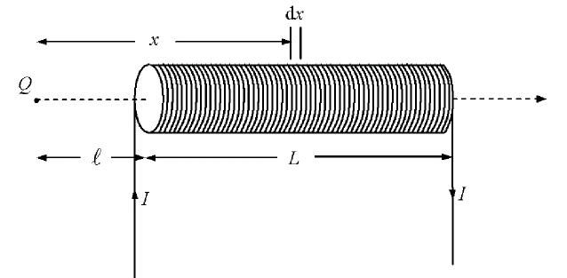
...............................(2)
where R is the radius of the solenoid.

Integrating equation (2), the magnetic flux density B due to the solenoid at Q is
<math xmlns="http://www.w3.org/1998/Math/MathML"><mi>B</mi><mo>=</mo><mfrac><mrow><msub><mi>&#x3BC;</mi><mn>0</mn></msub><mi>N</mi><mi>I</mi></mrow><mrow><mn>2</mn><mi>L</mi></mrow></mfrac><mfenced><mrow><mn>1</mn><mo>-</mo><mfrac><mi>l</mi><msqrt><msup><mi>l</mi><mn>2</mn></msup><mo>+</mo><msup><mi>R</mi><mn>2</mn></msup></msqrt></mfrac></mrow></mfenced></math>

Figure 13 shows the magnetic field B from the solenoid and the horizontal component <math xmlns="http://www.w3.org/1998/Math/MathML"><msub><mi>B</mi><mi>H</mi></msub></math> of the Earth's magnetic field acted perpendicular to each other at Q.
Experiment 7_Pic6

From the Figure 13
    <math xmlns="http://www.w3.org/1998/Math/MathML"><mi>tan</mi><mi>&#x3B8;</mi><mo>=</mo><mfrac><mi>B</mi><msub><mi>B</mi><mi>H</mi></msub></mfrac></math>
<math xmlns="http://www.w3.org/1998/Math/MathML"><mo>=</mo><mfrac><mrow><msub><mi>&#x3BC;</mi><mn>0</mn></msub><mi>N</mi><mi>I</mi></mrow><mrow><mn>2</mn><mi>L</mi><msub><mi>B</mi><mi>H</mi></msub></mrow></mfrac><mfenced><mrow><mn>1</mn><mo>-</mo><mfrac><mi>l</mi><msqrt><msup><mi>l</mi><mn>2</mn></msup><mo>+</mo><msup><mi>R</mi><mn>2</mn></msup></msqrt></mfrac></mrow></mfenced><mi>I</mi></math>
<math xmlns="http://www.w3.org/1998/Math/MathML"><mo>=</mo><mfrac><mrow><msub><mi>&#x3BC;</mi><mn>0</mn></msub><mi>N</mi><mi>I</mi></mrow><mrow><mn>2</mn><mi>L</mi><msub><mi>B</mi><mi>H</mi></msub></mrow></mfrac><mfenced><mrow><mn>1</mn><mo>-</mo><mfrac><mi>l</mi><msqrt><msup><mi>l</mi><mn>2</mn></msup><mo>+</mo><mstyle displaystyle="true"><mfrac><msup><mi>D</mi><mn>2</mn></msup><mn>4</mn></mfrac></mstyle></msqrt></mfrac></mrow></mfenced><mi>I</mi></math>
where diameter<math xmlns="http://www.w3.org/1998/Math/MathML"><mi>R</mi><mo>=</mo><mfrac><mi>D</mi><mn>2</mn></mfrac></math>

Apparatus:

i. Two wooden retort stands and clamps

ii. A cork and an optical pin

iii. A set of small bar magnet fixed with a pair of optical pins

iv. A plane mirror attached to a paper protractor

v. Thread of length about 40 cm

vi. A test-tube wound with copper wires

vii. A 1.5 V dry cell or any other stable power supply

viii. A (0-1A) d.c. ammeter

ix. A switch

x. A rheostat

xi. A pair of vernier calipers

xii. A micrometer screw gauge

xiii. Some connecting wires

Procedure:

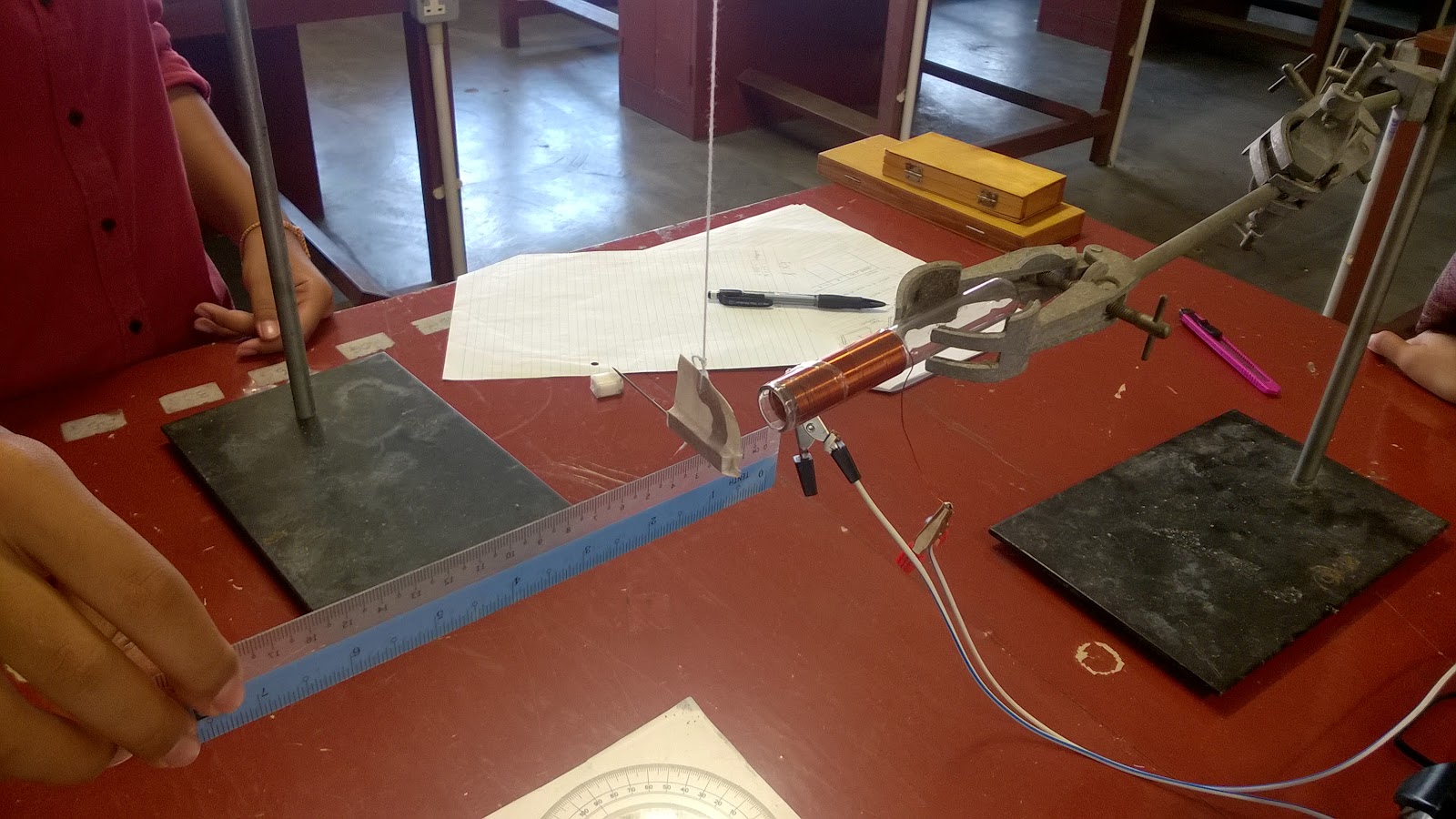
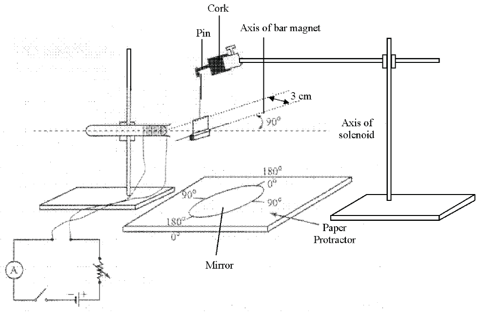
a) The cork with a pin is clamped to the retort stand. The bar magnet is hung from the pin using the thread supplied, so that the magnet stays at a height of about 3 cm above the table. The magnet is allowed to stay stationary and horizontal. The mirror is placed with the protractor with the 0° - 180° axis directly below the pins.

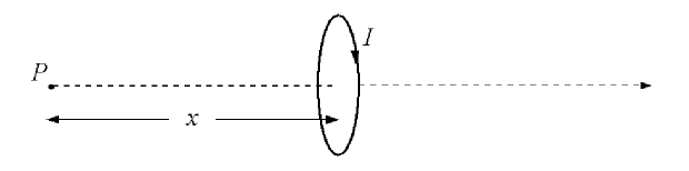
b) The solenoid is held by using the other clamp in a horizontal position at the same level with the magnet. The orientation of the solenoid is adjusted so that its axis is perpendicular to the axis of the magnet and one end of the solenoid is at 3.0 cm from the axis of the magnet. A rheostat, ammeter, power supply and switch is connected to the solenoid in series. The ammeter should be kept at least 50 cm from the magnet. The experiment is set up as shown in Figure 14.

c) The rheostat is adjusted to maximum resistance and the switch is then closed. The current I reading  of the ammeter is recorded and the average deflection of the magnet from the 0° - 180° axis is obtained.

d) The value of the resistance of the rheostat is decreased in stages so as to change the value of current I and then the corresponding value of θ is measured.

e) All the measurements for I, θ, and tan θ are recorded.

Experiment 7_Pic8
Figure 14

    e) A graph of <math xmlns="http://www.w3.org/1998/Math/MathML"><mi>tan</mi><mi>&#x3B8;</mi></math> against I is plotted.

    f) The gradient s of the graph of <math xmlns="http://www.w3.org/1998/Math/MathML"><mi>tan</mi><mi>&#x3B8;</mi></math> against I is calculated.

    g) The solenoid is removed to measure

                       i)The internal diameter D of the solenoid,

                      ii) Average diameter d of the wire used in the solenoid,

                     iii) The length  of the solenoid <math xmlns="http://www.w3.org/1998/Math/MathML"><msub><mi>L</mi><mi>s</mi></msub></math>.

                h) The values of d and <math xmlns="http://www.w3.org/1998/Math/MathML"><msub><mi>L</mi><mi>s</mi></msub></math> are used to estimate the number of turns N in the solenoid.

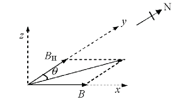
                i) The value of the horizontal componentBH of the Earth's magnetic field is calculated using the following estimation

    <math xmlns="http://www.w3.org/1998/Math/MathML"><msub><mi>B</mi><mi>H</mi></msub><mo>=</mo><mfrac><mrow><msub><mi>&#x3BC;</mi><mn>0</mn></msub><mi>N</mi></mrow><mrow><mn>2</mn><msub><mi>L</mi><mi>s</mi></msub></mrow></mfrac><mfenced><mrow><mn>1</mn><mo>-</mo><mfrac><mi>l</mi><msqrt><msup><mi>l</mi><mn>2</mn></msup><mo>+</mo><mstyle displaystyle="true"><mfrac><msup><mi>D</mi><mn>2</mn></msup><mn>4</mn></mfrac></mstyle></msqrt></mfrac></mrow></mfenced></math>

    Where <math xmlns="http://www.w3.org/1998/Math/MathML"><msub><mi>&#x3BC;</mi><mn>0</mn></msub><mo>=</mo><mn>4</mn><mi>&#x3C0;</mi><mo>&#xD7;</mo><msup><mn>10</mn><mrow><mo>-</mo><mn>7</mn></mrow></msup><mi>H</mi><msup><mi>m</mi><mrow><mo>-</mo><mn>1</mn></mrow></msup></math> and <math xmlns="http://www.w3.org/1998/Math/MathML"><mi>l</mi><mo>=</mo><mn>0</mn><mo>.</mo><mn>030</mn><mi>m</mi></math>

    .

    No comments: