Saturday, September 19, 2020

Syncronise

sut-suvgt 

this experiment is trying to show that the time taken to reach ground is the same for the projectile and free fall.


Trial 01

Trial 02


Trial 03


Wednesday, October 16, 2019

Experiment 13 Thin Lens

Experiment 13 Thin  Lens

Topic: Geometrical Optics Title: Thin lens

Purpose: To measure the refractive index of a lens 

Theory:
From the lens maker's formula, the focal length f of a thin lens is given by 
<math xmlns="http://www.w3.org/1998/Math/MathML"><mfrac><mn>1</mn><mi>f</mi></mfrac><mo>=</mo><mfenced><mrow><mi>n</mi><mo>-</mo><mn>1</mn></mrow></mfenced><mfenced><mrow><mfrac><mn>1</mn><msub><mi>r</mi><mn>1</mn></msub></mfrac><mo>-</mo><mfrac><mn>1</mn><msub><mi>r</mi><mn>2</mn></msub></mfrac></mrow></mfenced></math>
where n is the refractive index of the lens, and and are the radii of curvature of the surfaces of the lens.

The focal length of the lens can be determined by non-parallax method. The radii of curvature of the surfaces of the lens can be determined using a spherometer. The refractive index n can be found from the equation above.

The Figure 22 below shows a method to determine the radius of curvature using a spherometer with r the radius of curvature and x the distance between the centre leg and one of the fixed legs.
From Figure 22


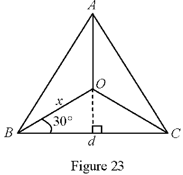
The four legs of spherometer can be represented as in Figure 23 where A, B and C are the fixed leg and O is the centre leg.
From Figure 23

The radius of curvature is obtained using the equation below. 

Apparatus:
(i)    A spherometer
(ii) A glass block
(iii) A convex lens
(iv) An optical pin
(v) A plane mirror
(vi) A retort stand with clamp
(vii) A half-metre rule

Procedure:

Part 1: To measure the radius of curvature by using a spherometer
(a) Place the spherometer on a plane glass block and lower the centre leg until it just touches the block.
(b) Measure and record this zero reading as .
(c) Place the spherometer on the curve surface of the lens. Adjust the centre leg until all the four legs touch the curved surface.
(d) Measure and record the reading of spherometer as . The difference in readings  gives the height of the centre leg above the other three.
(e) Press the three fixed legs on a pad of papers to make indentations.
(f) Draw a triangle as in Figure 23.
(g)    Measure and record the distance between the fixed legs d.
(h)    Determine the radius of curvature .
(i)    Repeat steps (c) and (d) to determine the radius of curvature

Part II: To determine the focal length of a convex lens
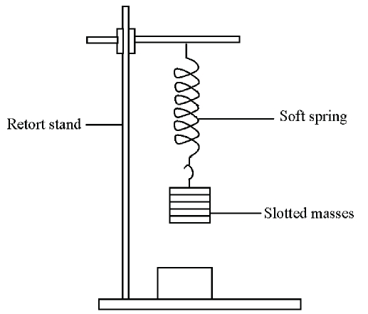
  (a)    Set-up the apparatus as in Figure 24.
(b)    Clamp an optical pin on the retort stand so that it is vertically above the centre of the convex lens.
(c)    Using non-parallax method, adjust the position of the optical pin until the image coincides with it.
(d)    Measure and record the height s of the pin above the plane mirror. The focal length of the lens f equals to s.
(e)    Determine the refractive index of the len.

Experiment 12 Waves motion

Experiment 12 
Topic: Waves motion 
Title: Standing waves
Objectives: To determine the mass per unit length of a thread 
Theory:
The frequency of a standing wave in a stretched thread is given by
    <math xmlns="http://www.w3.org/1998/Math/MathML"><mi>f</mi><mo>=</mo><mfrac><mn>1</mn><mrow><mn>2</mn><mi>L</mi></mrow></mfrac><msqrt><mfrac><mi>T</mi><mi>&#x3BC;</mi></mfrac></msqrt></math>
where f  is the frequency, T the tension in the thread, µ the mass per unit length and L the distance between two successive nodes.
Apparatus:
  1. A G clamp 
  2. An a.c. power supply (2 - 12 V, 50 Hz) 
  3. A ticker timer
  4. A pulley 
  5. Thread    
  6. A wedge  
  7. A light pan 
  8. Masses 1, 2, 5, 10, and 20 g 
  9. A metre rule 
  10. A triple beam balance

Procedure
(a)The apparatus is set up as in Figure below.

(b) Tie one end of the thread to the vibrator of the ticker timer and the other end to the light pan.
(c) The length of the thread from the vibrator to the pulley should not be less than 1.5 m.
(d) Add 10 g to the light pan and record the total mass M.
(e) Switch on the power supply.
(f) Place the wedge below the thread near to the pulley. Adjust the position of the wedge so that a steady stationary wave is observed.
(g) Measure and record the distance between two successive nodes.
(h) Add extra masses in increment of 1 g until another standing wave is observed. Measure and record P and M.
(i) Repeat step (h) to obtain at least five sets of reading. Tabulate L and W (W = Mg).
(k) Plot a graph of W against L2.
(l) Determine the mass per unit length μ of the thread used.

Data

Graph


Experiment 11 Oscillation

Experiment 11 Oscillation
Topic: Simple Harmonic Motion
Title: Oscillation 
Objective: To determine the mass of a spring
Theory:
A body of mass m is suspended on a coil spring with spring constant k is displaced from its equilibrium position and released.
If the amplitude of oscillation of the body is relatively small, its motion is simple harmonic and its period of oscillation T is given by
<math xmlns="http://www.w3.org/1998/Math/MathML"><mi>T</mi><mo>=</mo><mn>2</mn><mi>&#x3C0;</mi><msqrt><mfrac><mi>m</mi><mi>k</mi></mfrac><mo>+</mo><mfrac><msub><mi>M</mi><mi>k</mi></msub><mrow><mn>3</mn><mi>k</mi></mrow></mfrac></msqrt></math>
where m is the mass of the object and MS the mass of the spring.
Apparatus:
  1. A retort stand with clamp 
  2. Eight 20 g slotted masses
  3. A 50 g mass hanger
  4. A stopwatch
  5. A soft spring
  6. A weight to stabilizing the retort stand

Procedure:
(a)    Set-up the apparatus as shown in Figure below.
(b)    Attach the 50 g hook to the spring.
(c)    Displace the mass about 2-3 cm and release it.
(d)    Measure and record the time for 20 oscillations.
(e)    Repeat step (d) with different masses.
( f)    Plot a graph of T2 against m.
 (g)    From the graph, determine the mass of the spring, Ms.

Experiment 11_Pic1
Figure Exp11- 1. The spring that attach to retort stand have to be fix not moving and always vertical to the ground during 20 oscillation.